

How Do Surge Protective Device Factories Ensure Reliable Protection for Modern Electrical Systems?
2026-11-02
When a surge strikes, milliseconds decide whether your equipment survives or fails. Surge protective devices (SPDs) are the silent guardians of modern electrical systems, yet few people ask how their factories truly ensure that level of reliability. At ETEK, the answer isn't just a QC stamp—it's a chain of design rigor, component testing, and real-world simulation that most manufacturers never show you. In this post, we’ll pull back the curtain on the processes that separate dependable surge protection from a false sense of security.
Inside the Test Lab Where Real Lightning Strikes Are Recreated
Inside the test lab, the air carries a sharp, metallic tang of ozone long before anyone throws a switch. Rows of stacked capacitors and a towering Marx generator dominate the room, their polished electrodes aimed at a grounded test article mounted on a heavy concrete pad. Technicians move through a final checklist, checking insulation clearances and grounding straps with the same care a bomb squad might use.
When the command is given, the generator discharges in a fraction of a millisecond, releasing a brilliant white-blue arc that snaps across the gap with a crack loud enough to rattle the observation windows. Cameras running at tens of thousands of frames per second capture the leader stepping downward, branching and hesitating the way natural lightning does. Current shunts and Rogowski coils record peak currents that often exceed 100,000 amperes, while field sensors map the electromagnetic pulse radiating outward.
The point of reproducing such violence indoors is control. Real lightning is capricious—never striking the same spot twice on demand—but here engineers can hit a wind turbine blade, an aircraft radome, or a railway signaling enclosure again and again. That repeatability lets them watch how materials fail, how surge paths form, and whether protective systems actually clamp the energy before it reaches sensitive electronics. A few tests in this lab can compress years of exposure into a single afternoon.
Why Component Selection Decides Whether a Surge Protector Survives Its First Storm
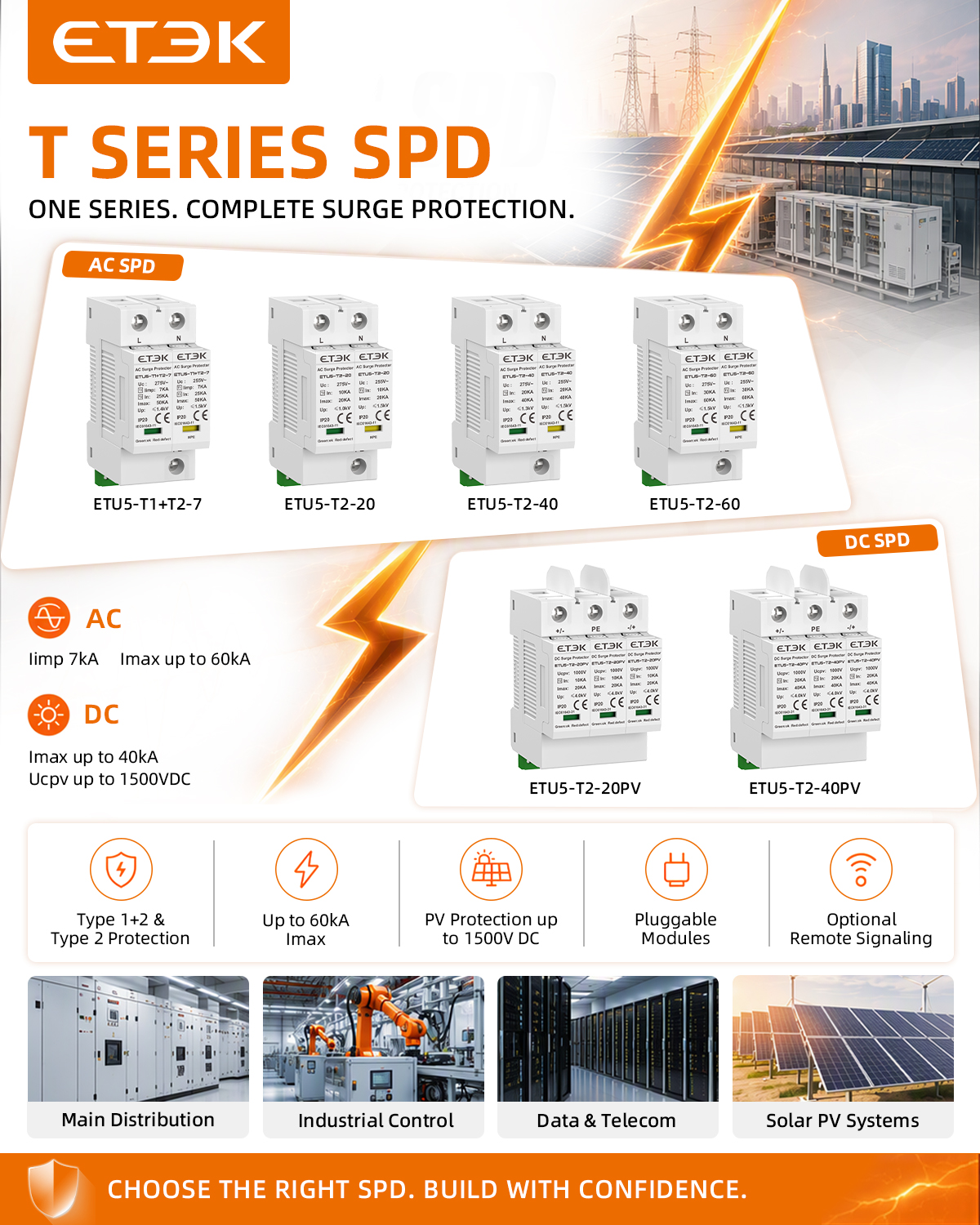
The first real lightning strike near your building is the moment a surge protector's true character shows. Cheap metal oxide varistors with loose tolerance ratings might clamp too late or absorb too little energy, leaving downstream electronics exposed before the protector itself fails. When the component batch varies by even a few joules, the whole protection strategy becomes a coin toss.
Thermal fuses and gas discharge tubes also play a quiet but decisive role. A poorly matched thermal fuse can open too slowly, letting the varistor overheat and crack its epoxy shell. Meanwhile, a gas discharge tube with the wrong spark-over voltage will either fire on normal voltage fluctuations—wearing itself out in months—or stay silent during a real surge, forcing the MOV to take a hit it was never sized for.
Board layout and lead length matter just as much as the parts themselves. Long traces between the input terminal and the protection components add inductance that delays clamping by microseconds, which is enough time for a fast transient to reach the power supply. If the surge protector cannot survive its first storm, the root cause is almost never the lightning; it is a component selection decision made weeks earlier in a design review.
What UL 1449 and IEC 61643 Actually Demand from Manufacturers
Manufacturers often assume that complying with one surge protection standard gives them automatic coverage under the other, but UL 1449 and IEC 61643 come from different regulatory philosophies. UL 1449, used primarily in North America, is heavily tied to building codes and insurance requirements. It forces manufacturers to publish precise voltage protection ratings, short-circuit current ratings, and specific type designations for each installation location. IEC 61643, on the other hand, operates under a broader international performance framework, demanding clear declarations of impulse current handling, voltage protection level, and behavior under temporary overvoltage conditions. A device designed and tested only for the IEC market will not simply slide through UL evaluation without additional testing and often significant redesign.
The actual test sequences reveal how differently the two standards push hardware. Under UL 1449, every surge protective device must prove it can handle repeated surges without losing its clamping ability, but it also has to survive extreme abnormal overvoltage tests that simulate lost neutral or miswiring scenarios. The product must be marked with a short-circuit current rating that reflects what the assembly, not just the internal components, can safely interrupt. IEC 61643 focuses more on impulse durability using specific waveforms like the 10/350 µs current for Class I devices or the 8/20 µs current for Class II devices, along with a separate temporary overvoltage test that can last for hours. Passing one set of tests does not demonstrate compliance with the other because the failure modes being explored are not identical.
A manufacturer's obligation does not end with a successful type test report. UL 1449 requires ongoing factory inspections, component traceability, and strict change control for anything that affects surge handling or fire safety. IEC 61643 demands similar production consistency through its own conformity assessment routes, but the specific documentation and marking formats differ. If a manufacturer swaps a metal oxide varistor supplier or changes the spacing of internal conductors, they must re-evaluate whether the certification remains valid under both schemes. This dual burden is why many companies maintain separate product lines for North American and international markets rather than trying to force a single design to satisfy both UL and IEC expectations at once.
How Smart Factories Design Surge Protectors That Sacrifice Themselves Safely
In a smart factory, every piece of equipment shares the same power backbone, so a single voltage spike can ripple through production lines in milliseconds. Surge protectors here are not just passive shields; they are engineered to absorb the excess energy and, if necessary, destroy their own internal components before the fault reaches sensitive machinery. The sacrificial elements—usually metal oxide varistors or gas discharge tubes—are chosen for predictable failure modes, so when they burn out, they do so without arcing or sending debris into nearby circuits.
The real difference comes from how these protectors are integrated into the factory's control network. Each unit reports its own health status, including how many surge events it has absorbed and whether its sacrificial parts are nearing end of life. When a protector finally sacrifices itself, the system isolates that branch automatically and flags the exact location for replacement, often before the next production shift begins. This turns a potential line shutdown into a routine maintenance task.
Design also accounts for physical containment. The protectors are built in modular housings with venting paths that direct hot gases away from other components, and the factory floor layout keeps them accessible but shielded from accidental contact. Because the failure is planned and contained, the rest of the line can keep running while the spent module is swapped out, making the sacrifice a controlled event rather than a cascading failure.
Matching Surge Ratings to the Specific Needs of Data Centers, Hospitals, and Solar Farms
Data centers run dense, redundant power paths where a single surge event can trip multiple PDUs and take down racks in seconds. Matching the surge rating here means accounting for the full fault current available at the service entrance and the inrush profiles of UPS bypass switches, not just slapping on a high-kA device. Hospitals add another layer: critical care equipment and imaging systems are sensitive to even low-energy transients, so the protection voltage rating needs to align with what the facility's most fragile microprocessor-based devices can tolerate without nuisance shutdowns.
Solar farms invert DC from long strings where induced surges from nearby lightning strikes can arrive from many directions. The surge rating has to reflect the maximum continuous operating voltage of the string plus headroom for cold-temperature voltage rise, and the SPD's thermal disconnect must coordinate with combiner box fusing. Rather than treating a high kA number as a one-size-fits-all answer, engineers should map the site's exposure, the impedance of the grounding system, and the equipment's actual withstand rating before settling on a specification.
Remote Monitoring and Predictive Maintenance That Keep Protection Active
A protection system that only gets checked during annual audits leaves too much room for silent failure. Remote monitoring changes that by continually pulling voltage, temperature, relay state, and trip circuit health from every connected device. Small anomalies show up before they become faults, so a corroded contact or a drifting power supply gets caught while there is still time to schedule a fix.
Predictive maintenance goes a step further by using historical operating data to identify which components are trending toward failure. Instead of replacing parts on a fixed calendar, maintenance happens when the actual condition calls for it. That keeps protection active without unnecessary outages, and it reduces the chance that a backup relay fails exactly when it is needed.
FAQ
Instead of relying only on datasheet numbers, established factories put each production batch through combination wave impulse tests (typically 8/20 µs and 10/350 µs waveforms) at rated current levels. They also run thermal stability trials where the unit is subjected to repeated surges while monitoring varistor temperature and leakage current. Units that drift beyond tolerance or show uneven clamping are pulled and dissected to verify solder joints and epoxy fill quality.
The trick is not simply choosing the lowest clamping voltage varistor. Engineers select MOV discs with carefully matched diameter, formulation, and coating thickness, then parallel multiple discs when necessary. They validate the trade-off using accelerated aging tests that simulate years of transient exposure in weeks. A factory may intentionally underrate a disc by 10–15% relative to its maximum surge rating to extend endurance while keeping let-through voltage within the protected equipment's immunity envelope.
Off-the-shelf MOVs and gas discharge tubes have wide tolerance spreads. A factory that matches components in-house can pair a GDT with an MOV so that the sparkover voltage and follow-on current behavior complement each other precisely. This reduces nuisance tripping and prevents the MOV from absorbing energy during slow-rising transients that the GDT can handle more efficiently. The matching process often involves binning parts by measured characteristics rather than nominal ratings.
Thermal disconnectors are the last line of defense when a varistor degrades to a short-circuit condition. Factories design them so that a solder joint with a controlled melting point releases a spring-loaded contact before the MOV can overheat and rupture. Advanced designs include both thermal and overcurrent protection, with arc quenching chambers to extinguish any follow-on current. Factory tests simulate end-of-life failure by deliberately overloading a sacrificial varistor and verifying the disconnector opens within milliseconds without enclosure damage.
They use programmable AC sources to replicate utility faults like lost neutral or phase-to-neutral overvoltage lasting from milliseconds to several hours. During these tests, engineers monitor the SPD's leakage current, surface temperature, and whether the internal protection operates. The goal is to confirm that the SPD either safely blocks the overvoltage or disconnects gracefully without creating a fire hazard. Data loggers record the exact trip time and energy dissipated, which feeds back into component selection and warning indicator thresholds.
Custom units often integrate surge protection with filtering, monitoring, and remote signaling. Factories build a functional prototype and run it through a battery of tests tailored to the installation environment: high-frequency noise injection for data lines, DC-side polarity reversal and ground-fault simulations for solar arrays, and load dump tests for generator-fed systems. The prototype is also subjected to vibration and thermal cycling to simulate transportation and rooftop conditions. Only after the prototype passes does the factory release the production document package, including assembly drawings that lock in wire routing and creepage distances.
Many SPD failures trace back to microscopic voids in solder joints or pinholes in conformal coating. To catch these, factories use automated optical inspection with angled cameras and X-ray imaging for multi-layer boards. They also perform partial discharge testing on encapsulated modules: a high-voltage AC is applied while sensors listen for tiny internal discharges that indicate air gaps or delamination. Batches with any detected anomalies are quarantined, and the root cause is traced to specific soldering profiles or coating viscosity adjustments.
Returned SPDs are treated as forensic evidence, not just warranty claims. Engineers measure residual varistor capacitance, inspect metal oxide grain boundaries under a microscope, and map burn patterns to reconstruct the surge path. This often reveals whether a failure came from a single massive strike, repetitive smaller surges, or a manufacturing inconsistency. The findings lead to concrete changes, such as increasing pad size on a PCB trace that repeatedly vaporized, or adding a conformal coating layer where humidity ingress accelerated degradation.
Conclusion
Inside a surge protective device factory, the work begins by recreating the destructive energy of a direct lightning strike in controlled test bays. Engineers fire 10/350 µs and 8/20 µs impulses into prototype after prototype, watching how metal oxide varistors, gas discharge tubes, and thermal disconnectors respond. The failures that show up here are not random; they trace back to component choices made weeks earlier on the assembly line. A varistor with the wrong clamping voltage or a poorly matched thermal fuse can mean the difference between a protector that shrugs off its first storm and one that quietly stops working. This is why UL 1449 and IEC 61643 are not treated as paperwork hurdles. The standards force manufacturers to verify voltage protection ratings, nominal discharge currents, and short-circuit withstand capabilities under repeatable, worst-case conditions. No factory wants to discover in a customer's breaker panel what it could have learned in the lab.
Beyond basic survival, the design philosophy has shifted toward making surge protectors sacrifice themselves safely rather than fail open or short unexpectedly. Smart factories now build in coordinated stages: a primary spark gap handles the massive first hit, a secondary varistor bank clamps the residual, and a final filter stage cleans up the noise. Every stage is sized against real load profiles, not generic assumptions. A data center's 480 V feed with row-level PDUs needs different coordination than a hospital's isolated power system or a solar farm's long DC strings. The answer is not one device fits all. Increasingly, surge protectors leave the factory with remote monitoring built in—thermal imaging sensors, leakage current tracking, and contact wear indicators feed data back to maintenance teams. The goal is not just to survive a lightning season but to know days or weeks in advance when a module is degrading, so replacement happens before the protection quietly expires.
Contact Us
Contact Person: Andy
Email: [email protected]
Tel/WhatsApp: +86 13356133008
Website: https://www.etek-china.com/