

Flange Penstock Gate Factory: Essential Guide to Quality Manufacturing and Selection
2026-11-02
When a penstock gate fails, the cost isn't just measured in repair bills—it's measured in lost water, halted operations, and compromised safety. That's why the difference between a gate that lasts decades and one that degrades prematurely often comes down to the factory behind it. Yet many buyers focus only on flange dimensions and pressure ratings, overlooking the hidden variables in casting, machining, and sealing that truly determine long-term performance. THT has spent years refining these exact processes, turning what others treat as commodity manufacturing into a controlled discipline. In this guide, we'll walk through the non-negotiable quality benchmarks for flange penstock gates, how to spot red flags in factory claims, and the selection criteria that separate a dependable asset from an operational liability. Whether you're upgrading an irrigation system or specifying for a hydro project, what you learn here could save you from the most expensive mistake—choosing a gate that looks right on paper but fails in the field.
Signs of a Trustworthy Flange Gate Builder on the Factory Floor
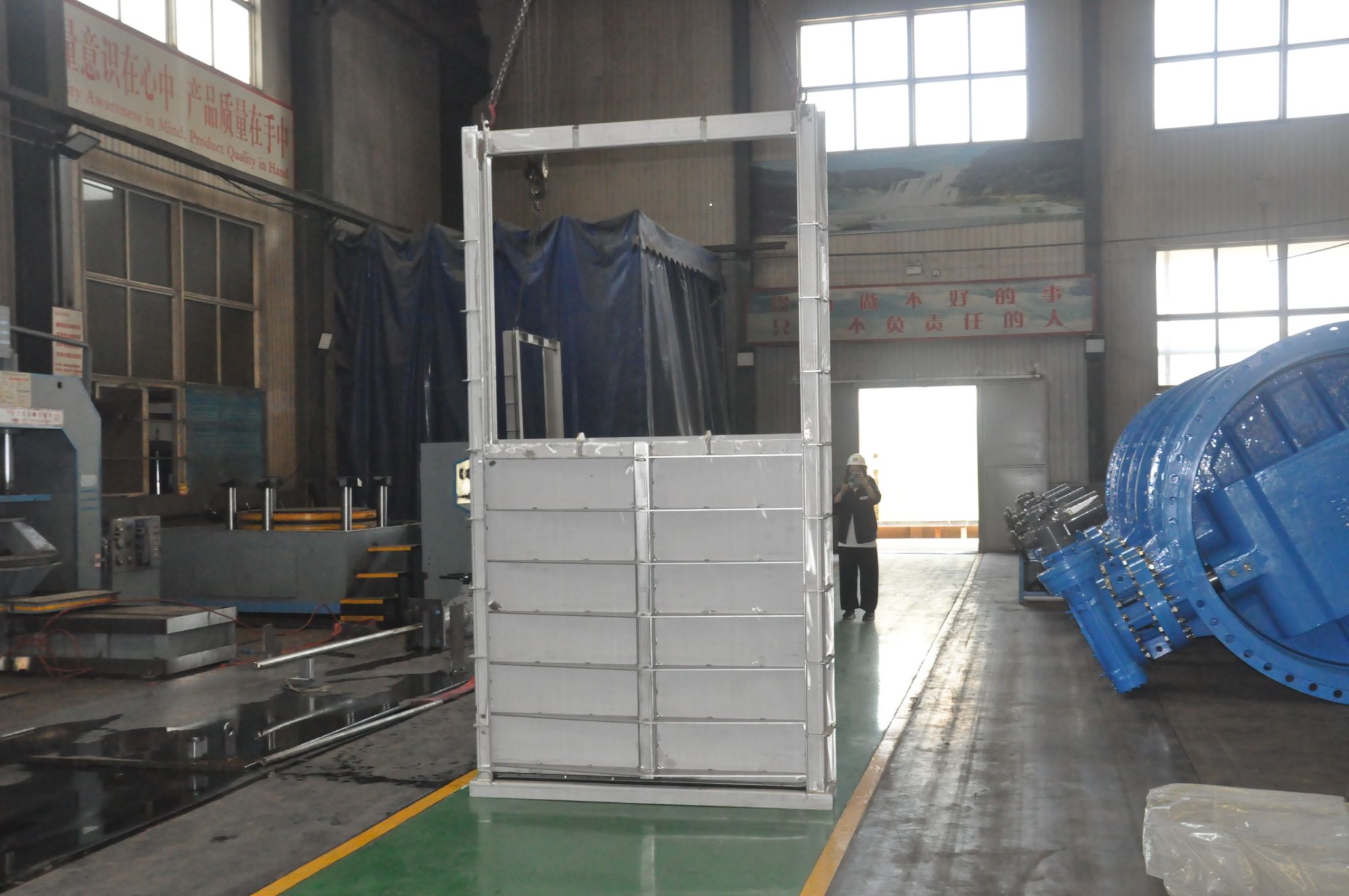
On a busy factory floor, a trustworthy flange gate builder shows itself through small details that are easy to walk past. Look at the material staging area. You should see traceability tags still attached to raw castings and forgings, not a pile of unmarked stock. Weld seams on the gate bodies are consistent and clean, not lumpy or undercut, which suggests the welders are following qualified procedures instead of rushing.
The pressure testing bay is another giveaway. A dependable builder keeps test fixtures and pressure gauges in plain view, with calibration stickers that are current. You might hear water or air hissing as a gate is cycled under load, and the operator records readings on a paper sheet or tablet rather than just nodding. If a gate is set aside with a red tag after a test, that is not a bad sign; it means failed units are quarantined and investigated, not quietly repainted and shipped.
Finally, watch how the crew handles the flange faces. A careful builder uses protective covers or wooden blocks so the machined surfaces are not sitting directly on concrete. Workers will wipe the faces with a solvent and inspect for nicks before assembly. If you see an inspector using a calibrated torque wrench on the bonnet bolts and checking the gate's travel with a dial indicator, the builder is serious about repeatable assembly, not just final appearance.
Material and Coating Decisions Beyond Standard Cast Iron
Beyond standard gray cast iron, material selection shifts based on thermal cycling, vibration damping versus strength, and weight. For components like brake drums or pump housings, compacted graphite iron (CGI) offers higher stiffness and thermal conductivity than gray iron while retaining much of its damping capacity. Ductile iron provides superior tensile strength and elongation for brackets or suspension parts where cast iron's brittleness becomes a failure risk. In lighter-duty applications, aluminum-silicon alloys reduce unsprung mass and improve heat dissipation, though they demand different machining parameters and corrosion protection.
Coating choices matter as much as substrate. Standard cast iron often relies on basic paint or oil seasoning, but aggressive environments call for engineered surfaces. Electroless nickel plating gives uniform corrosion resistance on complex castings without the buildup issues of electroplating. Thermal-sprayed ceramics such as alumina-titania shield exhaust or furnace parts from oxidation at temperatures where iron would scale rapidly. For sliding wear, PTFE-infused hard anodizing works on aluminum, while on iron substrates a phosphate conversion layer plus a dry-film lubricant can prevent galling without adding thickness that would alter clearances.
The right decision often involves a coupled material-coating system rather than upgrading either in isolation. A compacted graphite iron cylinder block, for instance, might use a plasma-sprayed bore coating to replace heavy cast-iron liners, cutting weight while improving scuff resistance. Similarly, a ductile iron steering knuckle coated with zinc-rich epoxy can outlast a standard cast iron part in salt-spray testing without requiring stainless steel. Matching the CTE, surface prep, and fatigue life of coating to the base metal avoids delamination and premature cracking under cyclic loads.
The Role of Sealing Geometry and Frame Rigidity in Leak Prevention
A gasket only works when its cross-section can actually fill the microscopic valleys left by machining or extrusion. Flat washers may seem simple, but a subtle crown or a tapered lip changes how the material flows under torque. If the profile is too tall relative to its width, the seal rolls or folds instead of compressing, leaving a direct path for fluid or gas. Round cords, for instance, concentrate load along a narrow line and can tolerate more surface roughness than a wide strip, but they also need a properly sized groove to prevent extrusion. Getting that groove depth and width wrong is often the real cause of a "bad" gasket.
Frame stiffness matters just as much, because no seal can make up for a flange that flexes between bolts. Picture a stamped sheet-metal cover with fasteners spaced twelve inches apart: under even moderate pressure, the edges curl upward between each bolt, reducing compression exactly where the seal is weakest. A thicker rim, an added rib, or a cast boss changes that behavior dramatically. When the frame doesn't deflect, the gasket sees a predictable, repeatable clamp load instead of a moving target.
The two factors also interact in less obvious ways. A very soft, tall seal can mask small amounts of frame bending on a first assembly, but after thermal cycling or creep, the material takes a set and the hidden unevenness shows up as a slow drip. In contrast, a rigid frame often allows a harder, lower-profile seal with better long-term stability. Designers who ignore either side of the equation usually end up chasing intermittent leaks that only appear on hot days or after vibration—conditions that punish any mismatch between geometry and stiffness.
Sizing for Flow, Pressure, and Real-World Conditions Beyond Pipe Diameter
Sizing a line purely by nominal diameter misses what actually governs performance, namely the velocity and pressure profile under operating loads. A pipe that looks generously sized on a datasheet can still generate velocities high enough to erode elbows or hammer valves when the real flow rate is pulsed rather than steady. Conversely, choosing one size up to be safe often delivers sluggish flow that complicates drainability, allows solids to settle, and wastes pumping energy.
Pressure ratings on pipe are only a starting point. The system sees transient spikes from rapid valve closure, suction-side cavitation in hot liquids, and compressibility-driven surges in gas service. Each fitting, branch, and elevation change adds localized pressure loss that rarely appears in a simple diameter table. If you ignore the pump or compressor curve and the cumulative effect of those minor losses, you may end up with a line that passes a static pressure test yet starves the process at demand.
Real-world conditions rarely match the clean, constant-temperature assumptions behind basic sizing formulas. Thermal expansion can overstress fixed anchors, abrasive particles can thin walls faster than corrosion allowance predicts, and future capacity increases often arrive sooner than expected. A better approach is to treat the initial diameter as a hypothesis, then stress-test it against viscosity shifts, low-flow turndown, slugging, and the unavoidable congestion of a crowded pipe rack.
What Quality Control Should Prove Before a Gate Leaves the Factory
A gate that clears the factory floor without a rigorous round of checks is a liability waiting to surface. The first thing any quality control team needs to establish is structural integrity under real-world stress. That means cycling the gate hundreds of times—opening, closing, slamming, and holding—while watching for sag, hinge wear, or any shift in alignment. Load tests aren't optional; a gate rated for a certain weight should face that weight plus a margin, with deflection measured against the original spec. Welds get inspected for penetration and porosity, not just visually but with dye penetrant or ultrasonic testing where the design calls for it. If a gate can't hold its line after this kind of abuse, it doesn't belong on a truck.
Beyond brute strength, there are the quieter failures that only show up later. Coatings and corrosion resistance need proof, not promises. A salt spray test tells you whether that powder coat or galvanized layer will still be there after a winter of road brine. Fasteners and moving parts—hinges, rollers, latch mechanisms, gas springs—should be checked for torque, play, and lubrication retention. Electrical components, where present, demand a functional test for continuity, insulation, and weather sealing. And don't forget the small things: edge finishing to prevent cuts, drainage holes that actually drain, and gaskets that seat evenly. These are the details that separate a gate that lasts a decade from one that rusts shut in two years.
Finally, quality control has to prove that the gate matches what was ordered. Dimensional checks against the drawing, including diagonal measurements for squareness and clearance gaps, catch fabrication drift before it becomes a fitment nightmare on a customer's vehicle. Documentation ties it together—serial numbers, test results, and material certs should travel with the gate. A factory that can hand you a folder of evidence for every weld and coating batch isn't just selling steel; it's selling confidence. That's the real gate pass: when every test says this one will behave exactly like the last one, and the next one after that.
Maintenance Habits That Keep Gates Moving and Prevent Seizure
Most gate problems build up quietly. Grit settles into the track, lubrication washes away, and bolts loosen just enough to change the way the panel rides. Spend ten minutes every month walking the full length of the gate. Clear the track with a stiff brush, check that the rollers sit flat, and push the gate manually about halfway to feel for rough spots. If it drags or sticks, fix that before running the motor again.
Use lubricants that do not attract debris. Heavy grease on a chain or roller becomes a grinding paste after a few weeks outdoors. A dry PTFE or silicone spray keeps moving parts slick without holding onto sand and leaf dust. Coat hinge pins and roller bearings lightly—more is not better—and wipe away any excess. After lubricating, run the gate through one full open-close cycle to spread the film evenly.
Finally, make seasonal adjustments part of the routine. Metal expands and contracts enough to alter alignment by a noticeable amount. When temperatures swing, check the guide wheels, tighten all mounting bolts, and adjust the open and close stops if the gate starts bouncing or straining. A gate that is allowed to slam against its stop will eventually damage the motor or shear a pin. Keep the manual release lever working, too; a quick pull test takes seconds and prevents a locked gate during the next power outage.
FAQ
Look for in-house machining of flange faces, documented material traceability, and a track record of supplying gates that fit existing penstock flanges without on-site rework. Dependable factories also test each gate under pressure before dispatch instead of relying on spot checks.
Many buyers assume standard flanges are universal, but penstock gates frequently need to match legacy pipework or unusual face-to-face dimensions. A factory that verifies your existing bolt circle, raised face height, and gasket seating before cutting metal will prevent most of those headaches.
For mildly corrosive water, a ductile iron body with a stainless steel seat and spindle is usually enough. For seawater or chemical exposure, consider full 316L stainless gates with PTFE gaskets and bronze bushings. Avoid mixing aluminum components with stainless fasteners in wet conditions.
Ask for weld procedure specifications and qualified welder certificates, not just a final visual report. Pay attention to the corners of the flange-to-body joint—those are where cracks start. A proper factory also performs dye penetrant or ultrasonic testing on critical welds for large gates.
Machined flange faces with a controlled spiral or concentric groove pattern give gaskets something to bite into, but too deep a groove can leak at low torque. The best factories specify a roughness range—typically 125 to 250 microinches Ra—and check it with a profilometer rather than relying on a visual comparison.
If your existing penstock has non-standard bolt spacing, a worn sealing surface, or a pressure rating that off-the-shelf gates cannot meet, a custom build is worth the wait. Custom also makes sense when you need a specific opening speed or an unusual stem extension, as long as the factory provides a detailed drawing approval stage.
Unmarked raw castings, flange faces with chatter marks, and a calibration sticker missing from the pressure test gauge are all warning signs. Also be wary of factories that cannot explain how they control flange flatness after welding, since heat distortion is the most common reason gates leak during commissioning.
Conclusion
Selecting a flange penstock gate demands more than a quick glance at the nameplate. A dependable factory reveals itself through practical signs: machining tolerances that hold up under a straightedge, weld profiles free of undercut, and a willingness to walk you through their test records instead of pointing to a brochure. Material choices matter far beyond the usual cast iron. Duplex stainless or epoxy-coated ductile iron often pays for itself when the water carries silt, salinity, or fluctuating pH. Coatings should be measured in mils and adhesion-tested, not just sprayed for appearance. Sealing geometry also separates a gate that drips from one that holds. Wedge angles, resilient seat compression, and frame stiffness determine whether leakage stays at zero when head pressure builds. A flimsy frame will flex and unseat the disc long before the rated pressure is reached.
Sizing should never stop at the pipe diameter. Real-world flow velocity, surge potential, and the possibility of partial opening under high differential pressure shape the right choice. A gate sized only by nominal bore can chatter, cavitate, or demand excessive actuation torque. Quality control before shipment needs to prove more than a hydrostatic shell test. Seat leakage at low and high pressure, cycle testing under load, coating thickness checks, and dimensional verification of the flange face are the minimum. Finally, maintenance habits decide whether the gate still moves after two years in a wet well. Regular cycling, greasing the stem, and flushing debris from the guides prevent seizure. A gate that cannot be exercised when needed is worse than no gate at all. By weighing factory floor evidence, materials, seal design, sizing logic, test proof, and upkeep, you end up with a penstock gate that earns its place in the line rather than one that merely fills the flange.
Contact Us
Contact Person: Su Zhang
Email: [email protected]
Tel/WhatsApp: +86-25219206
Website: https://www.tht-valve.com/