

Chip Resistor Recommended List for Efficient Circuit Design
2026-07-11
Selecting the right chip resistors can make or break your circuit's efficiency, but with countless options out there, where do you even start? We’ve curated a practical list of recommended types that balance precision, size, and power handling—perfect for streamlining your design process. From low-ohmic shunts to high-precision feedback paths, this guide highlights what truly matters. Need ultra-low resistance solutions? Milliohm offers specialized components that push the limits of efficiency. Dive in to see which resistors deserve a spot on your BOM.
Matching Resistors to Circuit Demands
Selecting the right resistor isn’t just about hitting a target resistance value—it’s about understanding how the component will behave under actual operating conditions. Every circuit imposes its own set of demands: tolerance for precision, power rating for heat dissipation, temperature coefficient for stability, and even parasitic inductance or capacitance when dealing with high frequencies. A resistor that looks perfect on paper can drift, overheat, or introduce noise if these factors are ignored.
For instance, a voltage divider in a sensitive analog front-end calls for tight tolerance and a low TCR to maintain accuracy across temperature swings, while a current-sensing resistor in a power supply must handle surges without sacrificing its low-resistance precision. Even the physical package matters—surface-mount resistors can crack under mechanical stress, and wirewound types might act like unwanted inductors in fast-switching circuits. Matching the resistor to such real-world constraints means balancing cost, size, and reliability long before the first prototype powers up.
Often, the best approach is to start with the most demanding parameter and work outward. If the circuit must operate from -40°C to 125°C, TCR becomes non-negotiable. If space is scarce, miniaturized thin-film parts might be worth the extra expense. And never underestimate the effect of ambient conditions—enclosure airflow, nearby heat sources, and even board flexing can turn a well-chosen resistor into a failure point. By treating selection as a design step rather than an afterthought, you ensure that each resistor quietly serves rather than undermines the circuit’s purpose.
When Size Matters: Picking the Right Package
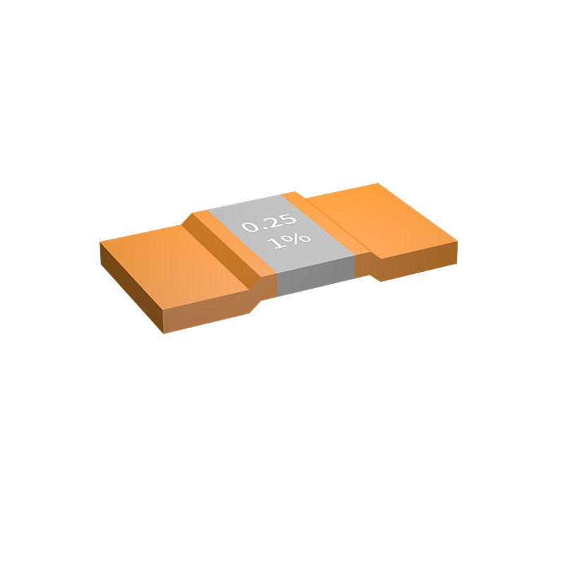
Choosing a package often comes down to dimensions that align with the product's journey and its final destination. Oversized boxes not only waste materials but also invite shipping surcharges that eat into budgets. Conversely, something too snug risks damage during transit, leaving customers frustrated. It's about finding that Goldilocks zone where every inch serves a purpose.
Beyond protection, size influences perception. A package that fits precisely conveys thoughtfulness, signaling that the brand cares about details. Compact designs reduce clutter in fulfillment centers and lower carbon footprints—subtle cues that resonate with eco-conscious buyers. The right proportions turn a mundane unboxing into a moment of quiet appreciation.
Practicality also meets psychology here: a package that’s just right feels intentional, not wasteful. It speaks to efficiency without shouting about it. From shelf presence to doorstep delivery, sizing is a quiet ambassador of your brand’s values. Sometimes, the best decision isn’t bigger or smaller—it’s smarter.
Dealing with Heat: Power Ratings in Practice
One of the first things engineers learn about component specifications is that the printed power rating is often more of a guideline than a guarantee. A resistor stamped with "1/2 watt" might safely handle that level of dissipation in open air at room temperature, but place it inside a sealed enclosure next to a voltage regulator and its actual capacity drops significantly. The practical rule becomes: derate early, derate generously. Instead of running a 0.5 W resistor at 90% of its rating, seasoned designers automatically shift to a 1 W part once calculated dissipation crosses the 250 mW mark. This headroom isn’t just about immediate failure—it’s about longevity, reduced noise, and avoiding thermal drift that can nudge a precision circuit out of spec.
Heat sinking, too, is never as simple as the thermal resistance formula suggests. That tidy RθJC number on a MOSFET datasheet looks straightforward until you factor in the interface material, mounting torque, and—most ignored—the temperature of the surrounding air creeping up after an hour of enclosure soak. In practice, the ambient temperature is not static. A power supply sitting in direct sunlight or mounted above a hot-running processor will see local ambient rise by 20°C or more, eating into your carefully calculated margin. This is why many field failures trace back not to wrong math but to optimistic assumptions about where the device would live. Successful thermal management demands actual temperature measurements on prototypes, not just spreadsheet simulations.
There's also the subtle trap of pulsed power. A transistor rated for 100 W might seem fine carrying 200 W pulses at a low duty cycle, but semiconductor junctions don’t respond linearly to average power—peak junction temperature can spike far above the steady-state value during each pulse. The result is a slow, cumulative degradation that standard reliability calculations miss because they look only at mean temperatures. Experienced power designers remedy this by examining transient thermal impedance curves, often adding extra margin for the die-attach and bond-wire fatigue that standard specs ignore. In high-reliability designs, the rule of thumb shifts to limiting peak junction temperature to 80% of the absolute maximum, even if the average looks safe. Only by respecting these practical boundaries—derating, real-world ambient, and transient behavior—do power ratings translate from paper promises into dependable hardware.
Resistor Arrays for Space and Cost Savings
Packing multiple resistors into a single component seems simple, but the real payoff shows up when board real estate gets tight. By consolidating several resistors into one array, you immediately slash the number of pick‑and‑place operations and trim the total footprint—often by half or more compared to discrete layouts. This compactness doesn’t just make the board look tidy; it lets you squeeze more functionality into the same area or shrink the overall product size without sacrificing performance.
The cost angle goes beyond lower component counts. With fewer solder joints and less board material wasted on routing, manufacturing defects drop, and assembly speeds pick up. Inventory management also gets a boost: one reel of resistor arrays replaces multiple reels of discretes, simplifying procurement and reducing the chance of mix‑ups. When every square millimeter and cent count, the shift to arrays quietly turns into a smarter, leaner design choice.
Tolerance and TCR: What Actually Counts
Resistance tolerance is often taken at face value—a simple ±1% or ±5% printed on the datasheet—but its real meaning is more nuanced. The tolerance figure applies at a specific reference temperature, typically 25°C, and doesn’t account for shifts caused by temperature fluctuations, self-heating, or aging. In many circuits, a 1% resistor might stay within its specified band only under benign lab conditions. Once the board warms up or the environment changes, that initial accuracy can quickly erode. Tolerance, then, is just one piece of a larger puzzle, and relying on it alone can lead to performance gaps.
Temperature Coefficient of Resistance (TCR) fills in a critical part of that puzzle. Expressed in parts per million per degree Celsius, TCR tells you how much the resistance drifts as temperature changes. A low TCR is non-negotiable in precision analog circuits, where even a modest temperature swing can throw off a measurement or a control loop. What actually counts is the combined effect: the initial tolerance plus the TCR-induced shift, plus other factors like power coefficient and long-term stability. When choosing a resistor, experienced engineers look beyond the tolerance figure and ask whether the part holds its value under all the stresses it will face—because that’s what determines real-world circuit accuracy.
Reliability Specs that Prevent Failures
Reliability isn't just a buzzword—it's baked into the design through rigorous specifications that anticipate real-world stress. Every component is tested beyond typical usage limits, ensuring it can handle voltage spikes, temperature swings, and prolonged operation without degradation. These specs aren't theoretical; they're derived from thousands of hours of accelerated life testing, where failures are analyzed and designed out of the final product.
One often-overlooked aspect is how these specifications account for cumulative wear. For instance, connectors are rated not just for a single insertion but for hundreds of mating cycles, maintaining low contact resistance even after repeated use. Thermal cycling specs ensure solder joints won't crack, while humidity and salt-spray tests protect against corrosion in harsh environments. By setting clear pass/fail criteria for each potential failure mode, the specs create a safety net that catches weaknesses before they become field failures.
The real value emerges when these specs are treated as living documents, updated with data from field returns and ongoing reliability tests. This feedback loop means the specs don't just prevent known failures—they evolve to stop future ones. It's a proactive approach that shifts reliability from a compliance checkbox to a continuous improvement engine, rooted in physics-of-failure analysis rather than generic industry standards.
FAQ
Beyond the obvious resistance value, you need to check the power rating to ensure it can handle the dissipated heat, tolerance for precision requirements, temperature coefficient of resistance (TCR) if the circuit experiences temperature swings, package size for PCB layout, and voltage rating to prevent breakdown. Also consider noise characteristics and long-term stability for critical applications.
It saves time by narrowing down thousands of options to proven, reliable components that balance performance and cost. Such a list often highlights parts with good availability, multiple sourcing, and known behavior in real-world designs, reducing the risk of supply chain issues or unexpected performance quirks.
Start with the power dissipation requirement—larger packages like 0805 or 1206 handle more heat. Then look at board space constraints: if density is critical, smaller sizes such as 0201 or 0402 are used, but they require careful soldering. Also factor in the voltage rating and the need for manual rework; smaller parts are harder to handle.
Values from the E24 or E96 series like 10kΩ, 1kΩ, 100Ω, 4.7kΩ, and 10Ω appear frequently. For pull-ups, 10kΩ is typical; for current sensing, low values like 0.1Ω or 0.01Ω are common. The list should include 0Ω jumpers for configuration options.
TCR indicates how much the resistance changes with temperature. In precision analog circuits or sensors, a low TCR (e.g., ±25 ppm/°C) is crucial to maintain accuracy over the operating range. For digital pull-ups, higher TCR (like ±200 ppm/°C) is usually acceptable, saving cost.
Thin-film resistors are typically recommended because they offer tighter tolerances (down to 0.01%), lower TCR (±10–25 ppm/°C), and better noise performance compared to thick-film types. Series like the Susumu RG or Panasonic ERA are common choices in this category.
You must ensure the resistor can dissipate the expected power with a safe margin. For example, if a resistor dissipates 0.1W, a 0.25W-rated 1206 might be used to prevent overheating and drift. In high-current paths, current-sense resistors with Kelvin terminals and power ratings of 1W or more are preferred to handle surges without failing.
Thick-film resistors like those from Yageo’s RC series or Vishay’s CRCW are widely used because they cover a broad range of values, have adequate performance for most non-critical nodes (tolerances from 1% to 5%), and are inexpensive. They strike a balance between cost, availability, and functional requirements.
Conclusion
Selecting chip resistors for a new design rarely boils down to simply matching ohms. To get a circuit working efficiently, you have to juggle electrical specs, physical constraints, and long-term reliability all at once. Resistance value is just the entry point; things get tricky when you start factoring in tolerance and TCR. In a precision analog front-end or a sensitive sensor path, a few parts per million drift can throw off calibration. That’s why a recommendation list that groups parts by tight tolerance and low TCR in common footprints saves so much time. At the same time, the push toward miniaturization means 0201 or 01005 packages are often necessary, yet these tiny resistors still need to handle real power dissipation. A shortlist of proven parts eliminates the guesswork of whether a specific 0402 can actually survive on a crowded board.
Power ratings on datasheets tell only part of the story; what matters is how the resistor behaves when packed next to heat-generating ICs. Derating curves and thermal resistance data become critical, and a well-chosen list accounts for this by highlighting resistors rated for elevated temperatures. When a design calls for many pull-ups or terminators, switching to resistor arrays cuts placement time and board real estate dramatically, though you must watch for unwanted coupling. Reliability specs like sulfur resistance or humidity tolerance often go ignored until field failures start piling up. A dependable recommended list bakes in these concerns ahead of time, so engineers aren’t reinventing the wheel for each project. It’s not just a catalog—it’s a curated toolkit that balances cost, performance, and ruggedness, letting you focus on the creative side of circuit design.
Contact Us
Contact Person: Yuying Gao
Email: [email protected]
Tel/WhatsApp: +86 18926013721
Website: https://en.milliohm.net/